Server-based Predictive Multiplayer Gaming (MPAI-SPG)
1 Introduction
Moving Picture, Audio and Data Coding by Artificial Intelligence (MPAI) is an international association with the mission to develop AI-enabled data coding standards. Research has shown that data coding with AI-based technologies is more efficient than with existing technologies.
The MPAI approach at developing AI data coding standards is based on the definition of AI Modules (AIM) with standard interfaces. AIMs operate on input data and produce output data, both having a standard format. AIMs can be combined and executed in an MPAI-specified AI-Framework. The MPAI-AIF standard is currently being developed after significant responses were received in response to a Call for MPAI-AIF Technologies [2] with associated Use Cases and Functional Requirements [1] issued on 2020/12/16.
By exposing standard interfaces, AIMs are able to operate in an MPAI AI Framework. However, their performance may differ depending on the technologies used to implement them. Therefore, MPAI believes that competing developers striving to provide more performing proprietary still interoperable AIMs will naturally create horizontal markets of AI solutions that build on and further promote AI innovation.
This document contains a Use Case and the corresponding Functional Requirements for the MPAI Server-based Predictive Multiplayer Gaming (MPAI-SPG) application area. The purpose of this Use Case is to minimise the audio-visual and gameplay discontinuities caused by high latency or packet losses during an online real-time game.
The current Use Case will be the target of Calls for Technologies. In the future MPAI may extend this Use Case of develop new ones falling in the scope of MPAI-SPG.
This document is structured in 7 chapters, including this Introduction.
| Chapter 2 | briefly introduces the AI Framework Reference Model and its six Components. |
| Chapter 3 | introduces the Use Case. |
| Chapter 4 | presents the Use Case with the following structure:
1. Reference architecture 2. AI Modules 3. I/O data of AI Modules 4. Technologies and Functional Requirements |
| Chapter 5 | gives relevant references |
| Chapter 6 | gives a basic list of relevant terms and their definition |
2 Terminology
Table 1 identifies and defines the terms used in the MPAI-CAE context.
Table 1 – MPAI-CAE terms
| Term | Acron. | Definition |
| Access | Static or slowly changing data that are required by an application such as domain knowledge data, data models, etc. | |
| AI Framework | AIF | The framework where AIM-based workflows are executed |
| AI Module | AIM | The basic processing element receiving AIM-specific inputs and producing AIM-specific outputs |
| Application area | A collection of homogeneous Use Cases | |
| Behaviour Engine | BE | The Engine that receives inputs from the different local or remote players, translates them into actions by the actors in the system and takes care of moving the actors managed by the CPU participating in the action at that moment. |
| Controller Data | CD | Data generated by Game I/O devices |
| Data Processing | DP | A legacy technology that may be used to implement AIMs |
| Execution | The environment in which AIM workflows are executed. It receives external inputs and produces the requested outputs both of which are Use Case specific | |
| Game Engines | GE | Engines receiving Game Messages from the Game State Engine and providing Game Messages back to the Game State Engine. |
| Game Message | GM | Messages sent to the Game Engines by the Game State Engine using its current Game State and the Controller Data. Game Engines send back new Game Messages GM’ |
| Game State | GS | A data structure containing all Game Messages at a given instant. |
| Game State Engine | GSE | A process managing the Game State of the game machine playing a game. |
| Management and Control | Manages and controls the AIMs in the AIF, so that they execute in the correct order and at the time when they are needed | |
| Storage | Data repository used to, e.g., store the inputs and outputs of the individual AIMs, data from the AIM’s state and intermediary results, and shared data among AIMs | |
| Use Case | UC | A description of an application that is served by an appropriate combination of AIMs executed in AIF |
| Physics engine | PE | The Engine that computes the behaviour of the world as different entities interact with each other, using the physics rules set by the developers |
| Rules engine | RE | The Engine manages the rules within the game system triggered by changes in the system occuring during interactions among players or CPU-controlled characters or by in-game messages independently of system state changes determined by the players |
3 The MPAI AI Framework (MPAI-AIF)
Most MPAI applications considered so far can be implemented as a set of AIMs – AI, ML and even traditional DP-based units – with standard interfaces assembled in suitable topologies to achieve the specific goal of an application and executed in the MPAI-defined AI Framework. MPAI is making all efforts to identify processing modules that are re-usable and upgradable without necessarily changing the inside logic. MPAI plans on completing the development of a 1st generation MPAI-AIF AI Framework in July 2021.
The MPAI-AIF Architecture is given by Figure 1.
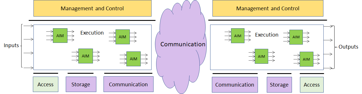
Figure 1 – The MPAI-AIF Architecture
MPAI-AIF is made up of 6 Components:
- Management and Control manages and controls the AIMs, so that they execute in the correct order and at the time when they are needed.
- Execution is the environment in which combinations of AIMs operate. It receives external inputs and produces the requested outputs, both of which are Use Case specific, activates the AIMs, exposes interfaces with Management and Control and interfaces with Communication, Storage and Access.
- AI Modules (AIM) are the basic processing elements receiving processing specific inputs and producing processing specific outputs.
- Communication is the basic infrastructure used to connect possibly remote Components and AIMs. It can be implemented, e.g., by means of a service bus.
- Storage encompasses traditional storage and is used to e.g., store the inputs and outputs of the individual AIMs, intermediary results data from the AIM states and data shared by AIMs.
- Access represents the access to static or slowly changing data that are required by the application such as domain knowledge data, data models, etc.
4 Use Case
A proper explanation of this Use Case requires an identification of the main components involved. This will be done following the evolution of gaming from offline to online to cloud gaming.
4.1 Offline gaming
At high level, an off-line game machine performs three steps:
- Receives inputs from the I/O devices.
- Processes the inputs.
- Produces a sequence of video frames.
A model of an off-line gaming is represented in Figure 2.
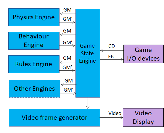
Figure 2 – Architecture of an off-line game machine
The following describes the off-line game machine operation based on Figure 2:
- The game I/O devices send Controller Data (CD) to the Game State Engine (GSE).
- The Game State Engine
- Uses Controller Data to create Game Messages (GM) carrying information about:
- Operation(s) to be executed in the game world, e.g., gamemessage method ==> movePlayerCharacter (unitID, direction, speed)
- The state of some objects in the game world, e.g., gamemessage status ==> playerCharacterPosition (xCoordinates, yCoordinates, energy):
- Sends Controller Data and/or Game Messages (depending on the type of Game Engine) to the Game Engines:
- The Physics Engine (PE) computes the behaviour of the world as different entities interact with each other, using the physics rules set by the developers. Examples of operations handles are: the behaviour of two colliding objects, the fall, the reaction of the different entities to the destruction of a part of their body.
- The Behaviour Engine (BE) receives inputs from the different local or remote players and translates them into actions by the actors in the system, and takes care of moving the actors managed by the CPU and who are participating in the action at that moment.
- Uses Controller Data to create Game Messages (GM) carrying information about:
- The Rules Engine (RE) manages the rules within the game system. Rules are triggered by changes in the system that occur during interactions among players or CPU-controlled characters or by in-game messages independently of system state changes determined by the players. E.g., at a certain time of the game the playing area available to the players decreases.
- Other Engine(s), if present.
- The Game Engines send their processed Game Messages (GM’) to the Game State Engine.
- The Game State Engine
- Creates the Game State, a data structure containing all Game Messages.
- The Client uses the GameState to generate a Video frame. The frame generation process does not concur in the creation, but only uses the Game State.
- Feedback (FB), e.g. haptic, to game I/O devices.
- The Video frame generator produces and renders a video frame
- Creates the Game State, a data structure containing all Game Messages.
4.2 Online Gaming
In online gaming, some of the functions carried out by an offline game machine are split between client and server.
4.2.1 Single player online gaming
The game operation becomes (see Figure 3):
- The Client:
- Receives the Controller Data from the game I/O devices.
- Sends the Controller Data to the server.
- The server:
- Computes the Game Messages?
- Sends Controller Data and/or Game Messages to the Game Engines.
- The Game Engines:
- Update the Game Messages (GM’).
- Send GM’ to the Game State Engine
- The Game State Engine
- Creates the Game State
- Sends the Game State to the Client.
- The Client creates and displays a new video frame
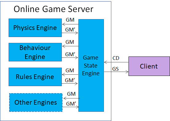
Figure 3 – Online gaming model (single player)
4.2.2 Multiplayer online gaming
The game operation becomes (see Figure 4):
- The Clients send Controller Data to Server
- The Game State Engine:
- Computes the Game Messages using the Controller Data (CD) from the Clients.
- Sends the Controller Data and/or the Game Messages to the Game Engines (GM).
- The Game Engines:
- Compute updated Game Messages (GM’).
- Send the updated Game Messages to the Game State Engine.
- The Game State Engine:
- Computes the updated Game State.
- Sends the new Game State to all clients.
- The Clients produce and display their video frames.
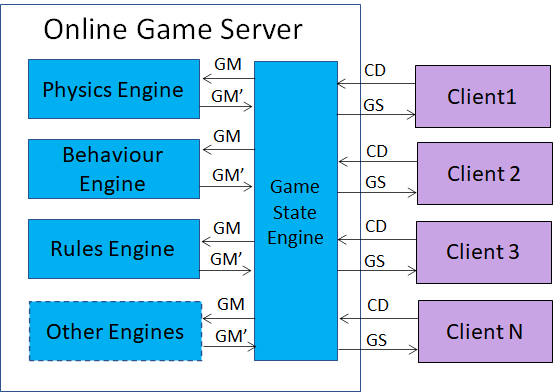
Figure 4 – Multiplayer online gaming model
4.3 Cloud gaming
In cloud gaming, the original functions of the offline Client are further split among the Thin Client, the Virtual Client and the Server.
Therefore, the operation of cloud gaming becomes (see Figure 5):
- The Thin Clients send Controller Data to their Virtual Clients.
- The Virtual Clients send Controller Data to the Server.
- The Game State Engine:
- Computes the Game Messages
- Sends Controller Data and/or Game Messages to the appropriate Game Engines.
- The Game Engines:
- Process the Game Messages.
- Send the updated Game Messages to the Game State Engine.
- The Game State Engine:
- Creates the Game State.
- Sends the Game State to the Virtual Clients.
- The Virtual Clients
- Process the new Game State.
- Create and compress the video frames
- Send the video frames to their Thin Clients.
- The Thin Clients display video.
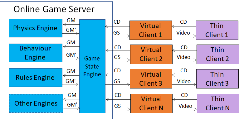
Figure 5 – Cloud gaming
4.4 The purposes of MPAI-SPG
MPAI-SPG is designed to serve two purposes:
- Mitigate the effects of the failed reception by the server of Controller Data from some (Thin) Clients caused by network disruption. This disrupts the user experience, sometimes seriously, because the server is unable to compute and communicate the Game Messages to the (Thin) Clients. AI can provide more effective ways to estimate the missing information.
- Detect false data sent by some (Thin) Clients (anticheating) who alter the Controller Data of their I/O devices to gain an unfair advantage. AI can also be used to detect such attempts.
5 Functional Requirements
5.1 Introduction
The Functional Requirements developed here adhere to the following guidelines:
- AIMs are defined to allow implementations by multiple technologies (AI, ML, DP)
- AI-based AIM will typically require a learning process, however, support for this process is not included in this document. MPAI may develop further requirements covering that process in a future extension of the document.
- AIMs can be aggregated in larger AIMs. Some data flows of aggregated AIMs may not necessarily be exposed any longer.
5.2 Reference architecture
The MPAI-SPG solution is depicted in Figure 7, applicable to cloud gaming and online gaming as well. In the following “Client” will be used to indicate both Virtual Clients and Clients.
The MPAI-SPG subsystem operates as follows
- The Controller Data and the Game State Engine enter the Game State Engine-AI.
- The Game State Engine-AI produces a set of GM*.
In normal conditions, the set of GM* should be close to the set of GM.
- The Controller Data and GM* feed the Game Engines AI’s.
- The Game State Engine-AI’s produce estimates of the set of Game Messages (GMp).
In normal conditions, the set of GMp should be close to the set of GM’.
- The green Game State Engine, functionally equivalent to the blue Game State Engine,
- Computes the predicted Game State (GSp).
In normal conditions, GSp should be close to GS.
- Sends the predicted Game State (GSp) to the Game State Engine.
- The Game State Engine
- Corrects its GS if
- GSp is too different than GS (anticheating).
- The Game State Engine was missing some Controller Data.
- Sends its current GS (GS) to the Game State Engine-AI.
- Corrects its GS if
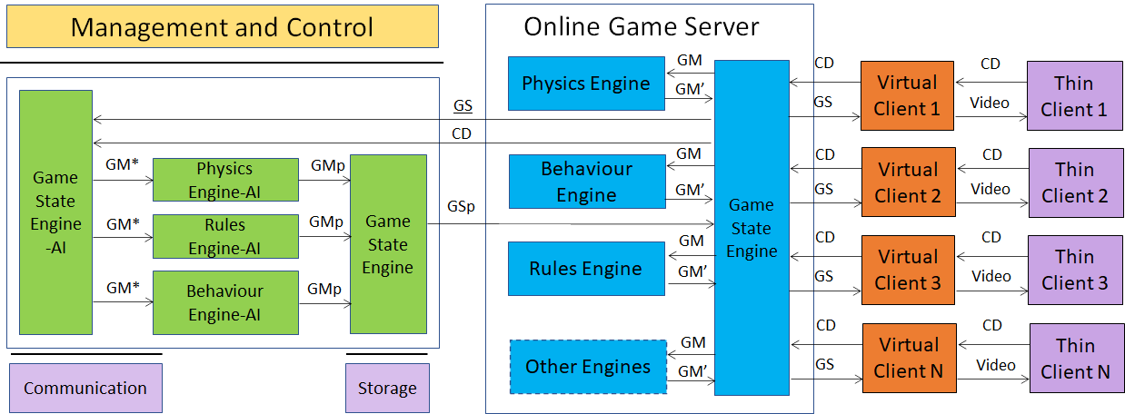
Figure 6 – The MPAI-SPG enhanced cloud gaming setting
Figure 7 is the reference model of MPAI-SPG.
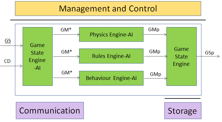
Figure 7 – The MPAI-SPG reference model
5.3 AI Modules
The AI Modules perform the functions described in Table 3.
Table 3 – AI Modules of Server-based Predicted Multiplayer Gaming
| AIM | Function |
| Game State Engine-AI | Produces predicted GM’ |
| Physics Engine-AI | Produces predicted GMp |
| Behaviour Engine-AI | Produces predicted GMp |
| Rules Engine-AI | Produces predicted GMp |
5.4 I/O interfaces of AI Modules
The I/O data are given in Table 4.
Table 4 – I/O data of Server-based Predicted Multiplayer Gaming AIMs
| AIM | Input Data | Output Data |
| Game State Engine-AI | CD
GS |
GM’ |
| Physics Engine-AI | GM’ | GMp |
| Behaviour Engine-AI | GM’ | GMp |
| Rules Engine-AI | GM’ | GMp |
5.5 Training
The Game State Engine-AI and the Engines-AI are trained using the Controller Data, the Game Messages, the GM’ generated by the the Engines and the Game State generated by real game players.
5.6 Technologies and Functional Requirements
5.6.1 Controller Data (CD)
| Digital input | controllerID, inputID, value (1/0), clientID, playerID |
| Analogue input | controllerID, inputID, value, clientID, playerID |
| Motion input | controllerID, inputID, valuesArray [], clientID, playerID |
Table 5 – Table of controllers
| # | Controller | Type | Inputs | Values | Examples |
| 1 | generic digital 4+1 | D | Up/Down/Left/Right/ Fire | 0: released
1: pressed |
Atari VCS controllers
Hyperkin Trooper |
| 2 | paddle | D | Fire | 0: released
1: pressed |
Commodore paddle |
| A | Ana+/Ana- | Fm -1 to +1 | |||
| 3 | … |
| Note1 | This table should be extended to include all controller types |
| Note2 | At this stage, the data (haptics etc.) coming into game device do not appear to require standardisation. |
5.6.2 Game Messages (GM)
There are two types of game messages. The fist concerns the operation applied to the data and the second the state
gamemessage (timestamp, methodName, SourceID, DestinationID, communicationType, param1, param2, …, paramK)
gamemessage (timestamp, state, SourceID, DestinationID, communicationType, param1, param2, …, paramJ)
5.6.3 GameState (GS)
GameState (timestamp, gameMessage1, gameMessage2, …, gameMessageK)
6 References
- MPAI-AIF Use Cases and Functional Requirements, N74; https://mpai.community/standards/mpai-aif/#Requirements