<-Go to AI Workflows Go to ToC ->
1 Functions
A CAE-6DF encoder produces and transmits Audio Scenes, a representation of the sound field captured. The input to the transmitter is either a set of microphone array signals (as described below) or a set of Ambisonics signals representing the sound field at distinct Points of View. An Audio Scene is based on:
- Identification of the microphone arrays’ Points of View (Position and Orientation) produced by a microphone array’s individual sensors. The output of the microphone array is represented by P(x,y,z,α,β,γ,t), where:
- P is a vector representing the amplitude of the sound pressure captured by individual sensors within a microphone array;
- x, y, z are the Cartesian coordinates wrt to a fixed, arbitrary reference origine in space identifying the position of the microphone array from which the positions of the individual sensors can be derived via Microphone Array Attributes;
- α, β, γ are the angles representing the orientation of the microphone array wrt the coordinate axes;
- t is the time.
- Decomposition of the Audio Scene into plane wave components and diffuse field components by applying two transformations of the Audio Scenes. This technical specification includes the formats of the components.
- Transform-domain representation of the plane wave components (direction and amplitude for the direct sound components) and of the diffuse field components.
- The diffuse field components are then converted to a time-domain representation and compressed.
- The output consists of the transform-domain direct sound components and the of the compressed diffuse field components and associated metadata that will be specified.
- Multiplex the data described in 5.
- Congruence of the Audio Scene with the Video Scene Descriptors is obtained by sharing the alignment of spatial and time coordinate axes.
2 Reference Model and its operation
Figure 1 depicts the Six Degrees of Freedom Encoder (CAE-6EN) Reference Model.
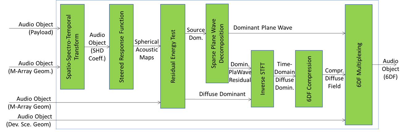
Figure 1 – Six Degrees of Freedom Encoder (CAE-6EN)
The MPAI CAE-6EN is the encoder that processes the payload included in an Audio Object with auxiliary information representing the Microphone Array Geometry and Device Scene Geometry to produce the 6DF representation which allows the production of an interpolated version of the sound field at the decoder.
The sequence of operations in CAE-6EN are as follows:
- Spatio-Spectro-Temporal Transform transforms the sound field captured in the form of time-domain multichannel audio signals captured by each microphone array into the spatio-spectro-temporal domain. This composite AIM first transforms each individual channel into a time-frequency representation; then, for each Microphone Array, it calculates the Spherical Harmonic Domain (SHD) representation, producing a new audio object which includes the complex-valued spherical harmonic decomposition (SHD) coefficients of the sound field as captured by using a multitude of microphone arrays. More specifically, the resulting audio object contains Spherical Harmonic Decomposition (SHD) Coefficients for each time-frequency bin where is the maximum SHD order.
- Steered Response Function carries out beamforming using the SHD coefficients included in the input audio object to generate a spherical acoustic map of the sound field at each microphone array position. This AIM uses beamforming coefficients which accentuate directions for which there are dominant sources and suppress directions for which there are not. The output of this AIM is a complex-valued spherical map for each microphone array and at each time-frequency bin.
- Residual Energy Test operates on the spherical acoustical maps to filter time-frequency bins for which there is only one dominant component for further analysis, those time-frequency bins which do not contain a single dominant component are also filtered to generate a set of time-frequency bins for which the diffuse field is considered to be dominant. The outputs of this AIM are therefore time-frequency bins that contain a single dominant source (Source Dominant) and time-frequency bins for which there is more than one source component, diffuse dominant (Diffuse Dominant). The output is a nested list of lists of tuples [ where and represent time and frequency indices, is the result of the residual energy test for the specific time-frequency bin and is the steered response function calculated for that time-frequency bin on an H-element HEALPix grid, near-uniformly tessellating the unit sphere. This AIM selects only those time-frequency bins for which is greater than a prescribed threshold.
- Sparse Plane Wave Decomposition receives time-frequency bins with a single dominant component as input and applies an appropriate sparse decomposition method to extract the direction and the amplitude of the dominant plane wave from each, as well as the residual. The residual will then be combined with the diffuse dominant part identified by the residual energy test AIM. The output is a nested list of lists of tuples [ where and represent time and frequency indices, is the result of the residual energy test for the specific time-frequency bin, h is the index of the direction on the HEALPix grid, near-uniformly tessellating the unit sphere, that corresponds to the direction of the dominant source, and are the real and imaginary parts of that source’s amplitude. The residual is calculated using non-dominant components produced by the employed sparse decomposition method.
- Inverse STFT receives the residual components from time-frequency bins which contain a single dominant component, as well as the time-frequency bins that contain only the diffuse dominant components. Combines them and transforms the result back into a time-domain diffuse-dominant set of signals. The produced diffuse dominant set of time domain signals can be represented as a complex-valued tensor where is the number of Microphone Arrays in the Device Scene Geometry, is the SH Decomposition order, is the duration of the Audio Object and is the sampling rate.
- 6DF Compression operates on the time-domain diffuse-dominant signals and compresses them to reduce the data size, producing the compressed diffuse field signals.
- 6DF Multiplexing packages the parametric representation of time-frequency bins that contain a dominant plane wave and the time-domain diffuse field components into a single MPAI CAE Audio Object with a 6DF payload. This AIM also packages the Device Scene Geometry originally input to the MPAI CAE-6EN for use at the decoder for sound field interpolation.
3 I/O data of AI Workflow
Table 1 gives the input and output data of 6DF Encoder.
Table 2 – Input/Output Data of 6DF-ENC
| Input | Description |
| Audio Object | Audio Data and Qualifier including Microphone Array Geometry and Device Scene Geometry which includes Microphone Array Audio Bundle and Capturing System Geometry as specified by the entries below. |
| Microphone Array Geometry | A Static Data Type representing the position of each microphone comprising a Microphone Array and specific characteristics such as microphone type, orientation, and the array type. See also |
| Audio Device Scene Geometry | A static list comprising tuples of Positions and Orientation of Q ³ 3 non-collocated Microphone Arrays having the same Microphone Array Geometry with which the elements of Microphone Array Audio Bundle are obtained. |
| Output | Description |
| Audio Object (6DF) | An Audio Object whose Audio Data is an Audio Scene comprising of: 1. 6DF Audio Data that includes: a) transform-domain amplitudes and directions of identified plane waves at each time-frequency bin for each Position triplet forming a triangle in a Delaunay triangulation of Capturing System Geometry, and b) a residual diffuse field components for each Position in the Recording System Geometry 2. 6DF Audio Qualifier specifying 6DF Audio Data represented according to this Technical Specification. |
4 Functions of AI Modules
The Functions of the AIMs required by 6DFEncoder are specified in Table 3.
Table 2 – Functions of AI Modules of A6DF Encoder
| AI Modules | Functions |
| Spatio-Spectro-Temporal Transform | Converts HOA format Microphone Array Audio into the time-frequency domain via a sliding Hann window followed by FFT (STFT) with overlap of at least 7/8 between blocks. The time frequency bin at frequency index, k and block time index n is indexed by the tuple (k, n). After that, Transform-domain HOA coefficients are converted to Transform-domain SHD coefficients. |
| Steered Response Function SRF | Using each time-frequency bin for each STFT, obtains the Steered Response Function for each Microphone Array on a spherical grid of size H described by the parameter h. |
| Residual Energy Test RENT | Selects time-frequency bins which predominantly contain a single sound source for triplets of Microphone Arrays in a Delaunay triangulation of the Device Scene Geometry. |
| Sparse Plane Wave Decomposition
|
Decomposes the selected time-frequency bins into a linear combination of at most P plane wave components called the Sparse Plane Wave Decomposition (SPWD) such that the dominant source is the plane wave with the highest magnitude and the residual components belong to the diffuse field. L1-based method can also be applied in this AIM. It also calculates the residual components for each time-frequency bins. |
| Inverse Short-Time Fourier Transform | (ISTFT) Performs the Inverse Short-Time Fourier Transform of the diffuse audio components. |
| 6DF Compression | Compresses the diffuse component of the sound field using an appropriate compression algorithm. |
| 6DF Multiplexing | Multiplexes each plane wave component, p at each time frequency bin (k, n) including its amplitude, A, and direction index, h, on a spherical grid and the output of the 6DF Compression. |
5 I/O Data of AI Modules
Table 4 – Input/Output Data of AI Modules
| AI Modules | Input | Output |
| Spatio-Spectro-Temporal Transform | Audio Object | SHD Transform Coefficients |
| Steered Response Function SRF | SHD Transform Coefficients | Spherical Acoustic Maps |
| Residual Energy Test RENT | Spherical Acoustic Maps | Source Dominant
Diffuse Dominant |
| Sparse Plane Wave Decomposition | Source Dominant
|
Dominant Plane Wave |
| ISTFT | Diffuse Dominant | Time-Domain Diffuse Dominant |
| 6DF Compression | Time-Domain Diffuse Dominant | Compressed Diffuse Field |
| 6DF Multiplexing | Dominant Sparse Plane Wave
Compressed Diffuse Dominant |
Audio Object |
6 AIW, AIMs, and JSON Metadata
Table 5 – AIW, AIMs, and JSON Metadata
| AIW | AIM | Name | JSON |
| CAE-6EN | Six Degrees of Freedom Encoder | File | |
| CAE-SST | Spatio-Spectro-Temporal Transform | File | |
| CAE-SRF | Steered Response Function | File | |
| CAE-RNT | Residual Energy Test | File | |
| CAE-SPW | Sparse Plane Wave Decomposition | File | |
| CAE-ISF | Inverse STFT | File | |
| CAE-AUC | Audio Compression | File | |
| CAE-6MX | 6DF Multiplexing | File |
7. Reference Software
The 6DF Encoder Reference Software can be downloaded from the MPAI Git.
8. Conformance Testing
| Receives | 6DF Audio Object | Shall validate against the Audio Object schema. The Qualifier shall validate against the Audio Qualifier schema. The values of any Sub-Type, Format, and Attribute of the Qualifier shall correspond with the Sub-Type, Format, and Attributes of the Audio Object Qualifier schema. |
| Produces | 6DF Audio Object | Shall validate against the Audio Object schema. The Qualifier shall validate against the Audio Qualifier schema. The values of any Sub-Type, Format, and Attribute of the Qualifier shall correspond with the Sub-Type, Format, and Attributes of the Audio Object Qualifier schema. |