<- Human-CAV Interaction (HCI) Go to ToC Autonomous Motion Subsystem (AMS)–>
7.1 Functions of Environment Sensing Subsystem
The Environment Sensing Subsystem (ESS):
- Uses all Subsystem devices to acquire as much as possible information from the Environment in the form of electromagnetic and acoustic data.
- Receives an initial estimate of the Ego CAV’s Spatial Attitude and Environment Data (e.g., temperature, pressure, humidity, etc.) from the Motion Actuation Subsystem.
- Produces a sequence of Basic Environment Representations (BER) for the duration of the travel.
- Passes the Basic Environment Representations to the Autonomous Motion Subsystem.
7.2 Reference Architecture of Environment Sensing Subsystem
Figure 4 gives the Environment Sensing Subsystem Reference Model.
Figure 4 – Environment Sensing Subsystem Reference Model
The typical sequence of operations of the Environment Sensing Subsystem AIW is:
- Spatial Attitude Generation computes the CAV’s Spatial Attitude using the initial Spatial Attitude provided by the Motion Actuation Subsystem and the GNSS.
- Environment Sensing Technology (EST)Produce – specific stream of data.
- Produce Environment Sensing Technology (EST)-specific Scene Descriptors, e.g., the RADAR Scene Descriptors.
- Access the Basic Environment Representation at a previous time interval to produce the EST-specific Scene Description.
- Integrate the Scene Descriptors from different Environment Sensing Technologies into the time-dependent Basic Environment Representation that includes Alert information.
Figure 4 assumes that Traffic Signalisation Recognition produces the Road Topology by analysing Camera Data. The model of Figure 4 can easily by extended to the case where Data from other ESTs is processed to compute or help compute the Road Topology.
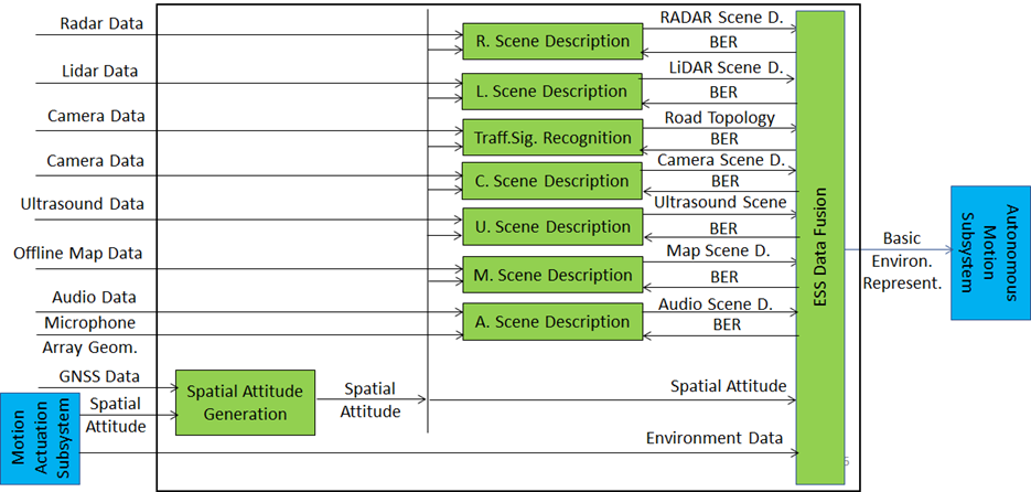
Figure 4 assumes that Environment Sensing Technologies are individually processed. An implementation may create a single Scene Descriptors for two or more ESTs.
7.3 I/O Data of Environment Sensing Subsystem
The currently considered Environment Sensing Technologies (EST) are:
- Global navigation satellite system or GNSS (~1 & 1.5 GHz Radio).
- Geographical position and orientation, and their time derivatives up to 2nd order (Spatial Attitude).
- Visual Data in the visible range, possibly supplemented by depth information (400 to 700 THz).
- LiDAR Data (~200 THz infrared).
- RADAR Data (~25 & 75 GHz).
- Ultrasound Data (> 20 kHz).
- Audio Data in the audible range (16 Hz to 16 kHz).
- Spatial Attitude (from the Motion Actuation Subsystem).
- Other environmental data (temperature, humidity, …).
Table 6 gives the input/output data of the Environment Sensing Subsystem.
Table 7 – I/O data of Environment Sensing Subsystem
| Input data | From | Comment |
| Radar Data | ~25 & 75 GHz Radio | Capture Environment with Radar |
| Lidar Data | ~200 THz infrared | Capture Environment with Lidar |
| Camera Data (2/D and 3D) | Video (400-800 THz) | Capture Environment with Cameras |
| Ultrasound Data | Audio (>20 kHz) | Capture Environment with Ultrasound |
| Offline Mapa Data | Local storage | cm-level data at time of capture |
| Audio Data | Audio (16 Hz-16 kHz) | Capture Environment or cabin with Microphone Array |
| Microphone Array Geometry | Microphone Array | Microphone Array disposition |
| Global Navigation Satellite System (GNSS) Data | ~1 & 1.5 GHz Radio | Get Pose from GNSS |
| Spatial Attitude | Motion Actuation Subsystem | To be fused with GNSS data |
| Other Environment Data | Motion Actuation Subsystem | Temperature etc. added to Basic Environment Representation |
| Output data | To | Comment |
| Alert | Autonomous Motion Subsystem | Critical last minute Environment Description from EST (in BER) |
| Basic Environment Representation | Autonomous Motion Subsystem | ESS-derived representation of external Environment |
7.4 Functions of Environment Sensing Subsystem’s AI Modules
Table 7 gives the functions of all AIMs of the Environment Sensing Subsystem.
Table 8 – Functions of Environment Sensing Subsystem’s AI Modules
| AIM | Function |
| RADAR Scene Description | Produces RADAR Scene Descriptors from RADAR Data |
| LiDAR Scene Description | Produces LiDAR Scene Descriptors from LiDAR Data |
| Traffic Signalisation Recognition | Produces Road Topology of the Environment from Camera and LiDAR Data. |
| Camera Scene Description | Produces Camera Scene Descriptors from Camera Data |
| Ultrasound Scene Description | Produces Ultrasound Scene Descriptors from Ultrasound Data. |
| Online Map Scene Description | Produces Online Map Data Scene Descriptors from Online Map Data. |
| Audio Scene Description | Produces Audio Scene Descriptors from Audio Data. |
| Spatial Attitude Generation | Computes the CAV Spatial Attitude using information received from GNSS and Motion Actuation Subsystem with respect to a predetermined point in the CAV defined as the origin (0,0,0) of a set of (x,y,z) Cartesian coordinates with respect to the local coordinates. |
| Environment Sensing Subsystem Data Fusion | Selects critical Environment Representation as Alert; produces CAV’s Basic Environment Representation by fusing the Scene Descriptors of the different ESTs,
The Basic Environment Representation (BER) includes all available information from ESS and MAS that enables the CAV to define a Path in the Decision Horizon Time. The BER results from the integration of: 1. The different Scene Descriptors generated by the different EST-specific Scene Description AIMs. 2. Environmental data. 3. The Spatial Attitude of the Ego CAV as estimated by the Motion Actuation Subsystem. |
 |
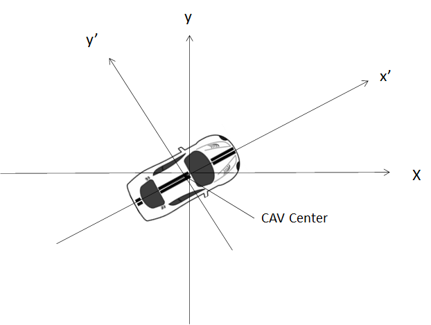 |
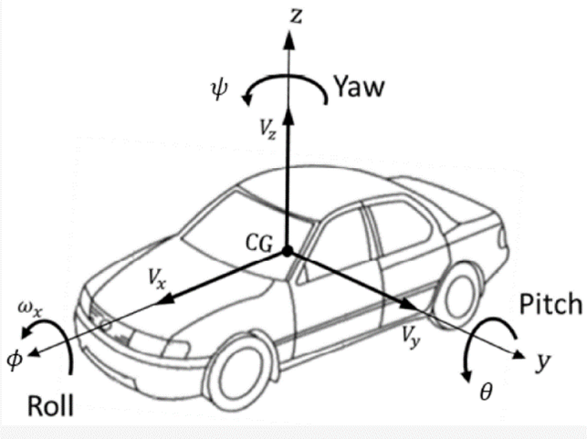
| Figure 5 – Roll, Pitch, and Yaw in a vehicle [6] | Figure 6 – Spatial Attitude in a CAV |
7.5 I/O Data of Environment Sensing Subsystem’s AI Modules
For each AIM (1st column), Table 8 gives the input (2nd column) and the output data (3rd column) of the Environment Sensing Subsystem.
Table 9 – I/O Data of Environment Sensing Subsystem’s AI Modules
| AIM | Input | Output |
| Radar Scene Description | Radar Data
Basic Environment Representation |
Radar Scene Descriptors |
| Lidar Scene Description | Lidar Data
Basic Environment Representation |
Lidar Scene Descriptors |
| Traffic Signalisation Recognition | Camera Data
Basic Environment Representation |
Road Topology |
| Camera Scene Description | Camera Data
Basic Environment Representation |
Lidar Scene Descriptors |
| Ultrasound Scene Description | Ultrasound Data
Basic Environment Representation |
Ultrasound Scene Descriptors |
| Map Scene Description | Offline Map Data
Basic Environment Representation |
Map Scene Descriptors |
| Audio Scene Description | Audio Data
Basic Environment Representation |
Audio Scene Descriptors |
| Spatial Attitude Generation | GNSS Data
Spatial Attitude form MAS |
Spatial Attitude |
| Environment Sensing Subsystem Data Fusion | RADAR Scene Descriptors
LiDAR Scene Descriptors Road Topology Lidar Scene Descriptors Ultrasound Scene Descriptors Map Scene Descriptors Audio Scene Descriptors Spatial Attitude Other Environment Data |
Basic Environment Representation
Alert |
<- Human-CAV Interaction (HCI) Go to ToC Autonomous Motion Subsystem (AMS)–>
© Copyright MPAI 2022-23. All rights reserved