5.1 Human-CAV Interaction (HCI)
5.2 Environment Sensing Subsystem (ESS)
5.4 Autonomous Motion Subsystem (AMS)
5.5 Motion Actuation Subsystem (MAS)
1 Use Cases
MPAI-CAV seeks to standardise all components that enable the implementation of a Connected Autonomous Vehicle (CAV), i.e., a mechanical system capable of executing the command to move its body autonomously – save for the exceptional intervention of a human – based on the analysis of the data produced by a range of sensors exploring the environment and the information transmitted by other sources in range, e.g., CAVs and roadside units (RSU).
Figure 2 depicts the context where a CAV operates.
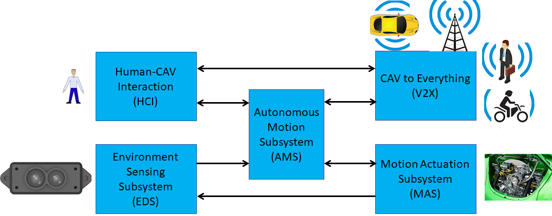
Figure 2 – The environment where a CAV operates
MPAI-CAV includes 5 Use Cases that correspond to the 5 main subsystems of a Connected Autonomous Vehicle:
1.1 Human-CAV Interaction (HCI)
1.1.1 Use Case description
Human-CAV Interaction operated based on the principle that the CAV is impersonated by an avatar, selected/produced by the CAV rights-holder. The visible features of the avatar are head face and torso, and the audible feature is speech that embeds as much as possible the sentiment, e.g., emotion, that would be displayed by a human driver.
The CAV’s avatar is reactive to:
- The Environment, e.g., it can show an altered face because a human driver has done what it considers an improper action.
- A human, e.g., it shows an appropriate face to a human in the cabins who has made a joke.
Other forms of interaction are:
- CAV authenticates human interacting with it.
- A human issues commands to a CAV, e.g.:
- Commands to Autonomous Motion Subsystem, e.g.: go to a Waypoint or display Full World Representation (see 5.3), etc.
- Other commands, e.g.: turn off air conditioning, turn on radio, call a person, open window or door, search for information etc.
- A human entertains a dialogue with a CAV, e.g.:
- CAV offers a selection of offers to human (e.g., long but safe way, short but likely to have interruptions).
- Human requests information, e.g.: time to destination, route conditions, weather at destination etc.
- Human entertains a casual conversation.
- A CAV monitors the passenger cabin, e.g.:
- Physical conditions, e.g.: temperature level, media being played, sound level, noise level, anomalous noise, etc.
- Passenger data, e.g.: number of passengers, ID, estimated age, destination of passengers.
- Passenger activity, e.g.: level of passenger activity, level of passenger-generated sound, level of passenger movement, emotion on face of passengers.
- Passenger-to-passenger dialogue, two passengers shake hands, or passengers hold everyday conversation.
It is important to point out that, regardless of the fact that vehicles can exhibit different levels of autonomy, the exhibited autonomy should always be adjustable [1]. The system should recognise people as intelligent agents it should inform and be informed by. A CAV should be able to change its level of autonomy to one of several levels during its operation. Such an adjustment may be initiated by a human, another system, or the CAV itself. An important benefit of adjustable, user-centered autonomy is increased user acceptance of the system [39].
1.1.2 Reference architecture
Figure 4 represents the Human-CAV Interaction (HCI) Reference Model. The following is noted:
- A combination of Conversation with Emotion and Multimodal Question Answering AIMs with gesture recognition capabilities covers most Human-CAV Interaction needs.
- Additional AIMs can be added should new HCI interactions be required.
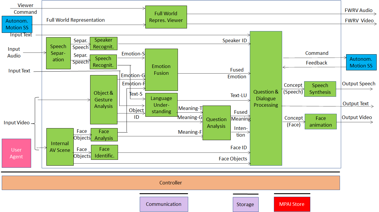
Figure 4 – Human-CAV Interaction Reference Model
The speech of the human is separated from the audio captured from the environment; speaker and speech are recognised; meaning and emotion are extracted from speech; gesture and object information are extracted from video; human is identified, and emotion and meaning extracted from video of the face; emotions are fused; meanings are fused and intention derived to produce speech and face of the avatar interacting with humans; position of humans is computed to provide a realistic gazing. Additionally, human commands and responses from Autonomous Motion Subsystem are processed; Full World Representation is presented to let humans get a complete view of the Environment.
Depending on the technology used (data processing or AI), the AIMs in Figure 4 may need to access external information, such as Knowledge Bases, to perform their functions. While not represented in Figure 4, they will be identified, if required, in the AI Modules subsection.
1.1.3 Input and output data
Table 2 gives the input/output data of Human-CAV Interaction.
Table 2 – I/O data of Human-CAV Interaction
| Input data | From | Comment |
| Audio | User Outdoor | User authentication
User command |
| Text | User Outdoor | User authentication
User command |
| Text | Passenger Cabin | Social life of user
Commands or interaction with CAV |
| Audio | Passenger Cabin | User’s social life
Commands or interaction with CAV |
| Video | Passenger Cabin | Social life of user
Commands or interaction with CAV |
| Full World Representation | Autonomous Motion SS | For processing by FWR Viewer |
| Output data | To | Comments |
| Text | Autonomous Motion SS | Commands to be executed |
| Synthetic Speech | Passenger Cabin | CAV’s response to passengers |
| Synthetic Face | Passenger Cabin | CAV’s response to passengers |
| Full World Representation | Passenger Cabin | For passengers to view external world |
1.1.4 AI Modules
Table 3 gives the AI Modules of the Human-CAV Interaction depicted in Figure 4.
Table 3 – AI Modules of Human-CAV interaction
| AIM | Function |
| Speech detection and separation | 1. Separates relevant speech vs non-speech signals
2. Detects request for dialogue. |
| Speaker identification | Recognises speaker. |
| Speech recognition | 1. Analyses the speech input.
2. Generates text and emotion output. |
| Object and gesture analysis | 1. Analyses video to identify object.
2. Produces the ID of the object in focus. 3. Analyses video. 4. Produces motion and meaning of gesture. |
| Face recognition | 1. Analyses the video of the face of a human.
2. Recognises the human’s identity. |
| Face analysis | 1. Analyses the video of the face of a human.
2. Extracts emotion and meaning. |
| Language understanding | 1. Analyses natural language expressed as text using a language model (embedded in AIM).
2. Produces the meaning of the text. 3. Identifies Object ID. |
| Emotion recognition | Produces Final Emotion by fusing Emotions from Speech, Face and Gesture. |
| Question analysis | 1. Fuses Meanings of Speech, Face and Gesture
2. Analyses the meaning of the sentence. 3. Determines the Intention. 4. Outputs Final Meaning. |
| Question & dialog processing | 1. Receives Speaker ID and Face ID.
2. If speaker ID and face ID match, then: a. Produces a command to Autonomous Motion SS b. Analyses user’s emotion, intention, meaning and/or question, text. c. Produces Concept (speech) and Concept (face). 3. Else, responds appropriately. |
| Speech synthesis | Converts Concept (Speech) to Output Speech. |
| Face animation | Converts Concept (Face) to Output Video. |
| Full World Representation Viewer | 1. Receives Full World Representation (FWR)
2. Presents a FWR view as instructed by human via FWR Commands. |
1.2 Environment Sensing Subsystem (ESS)
1.2.1 Use Case description
The purpose of the ESS is to acquire all sorts of electromagentic and acoustic data directly from its sensors and other physical data of the Environment (e.g., temperature, pressure, humidity etc.) and of the CAV (Pose, Velocity, Acceleration) from Motion Actuation Subsystem with the main goal of creating the Basic World Representation.
1.2.2 Reference architecture
Figure 5 gives the Environment Sensing Subsystem Reference Model.
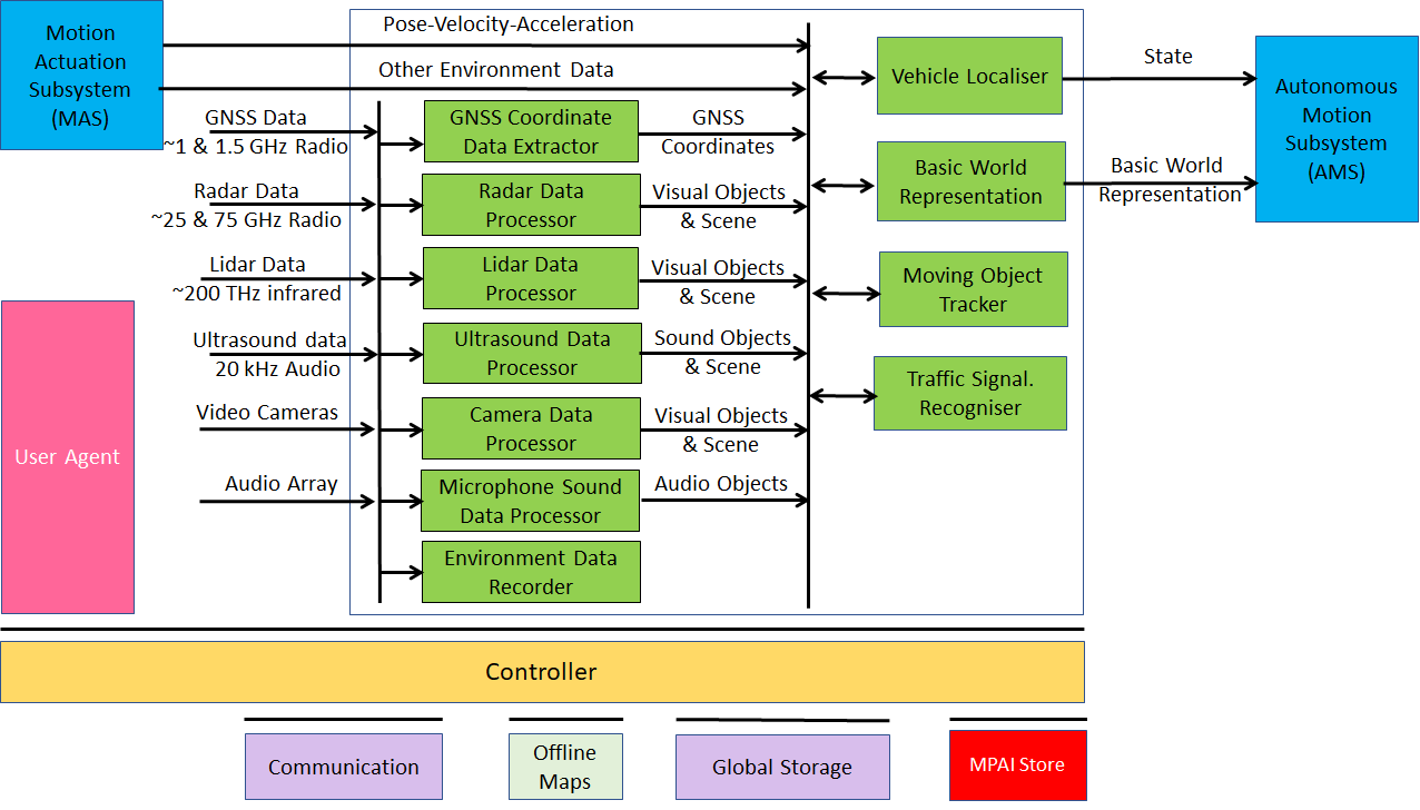
Figure 5 – Environment Sensing Subsystem Reference Model
The typical series of operations carried out by the Environment Sensing Subsystem (ESS) is given below. The sequential description of steps does not imply that an action is only carried out after the preceding one has been completed.
- The CAV gets its Pose and other environment data from:
- Global Navigation Satellite System (GNSS).
- Vehicle Localiser in ESS.
- Other Environment data (e.g., weather, air pressure etc.).
- Coordinates data (Pose, Velocity, Acceleration).
- The CAV creates a Basic World Representation (BWR) by:
- Acquiring available Offline maps of its current Pose.
- Fusing Visual, Lidar, Radar and Ultrasound data.
- Updating the Offline maps with
- Other static objects.
- All moving objects.
- All traffic signalisation.
- The CAV compresses and stores a subset of the sensor data on board the ESS.
1.2.3 Input and output data
Table 4 gives the input/output data of Environment Sensing Subsystem.
Table 4 – I/O data of Environment Sensing Subsystem
| Input data | From | Comment |
| Pose-Velocity-Acceleration | Motion Actuation Subsystem | To be fused with GNSS data |
| Other Environment Data
|
Motion Actuation Subsystem | Temperature etc. to be added to Basic World Representation |
| Global Navigation Satellite System (GNSS) | ~1 & 1.5 GHz Radio | Get Pose from GNSS |
| Radio Detection and Ranging (RADAR) | ~25 & 75 GHz Radio | Get RADAR view of Environment |
| Light Detection and Ranging (LIDAR) | ~200 THz infrared | Get LiDAR view of Environment |
| Ultrasound | 20 kHz Audio | Get 20 kHz view of Environment |
| Cameras (2/D and 3D) | Video (400-800 THz) | Get visible view of Environment |
| Microphones | 16 Hz-16 kHz sound | Get Audible view of Environment |
| Output data | To | Comment |
| State | Autonomous Motion Subsystem | For Route, Path and Trajectory |
| Basic World Representation | Autonomous Motion Subsystem | Locate CAV in Environment |
1.2.4 AI Modules
Table 5 gives the AI Modules of Environment Sensing Subsystem.
Table 5 – AI Modules of Environment Sensing Subsystem
| AIM | Function |
| GNSS Data Coordinate Extractor | Computes global coordinates of CAV. |
| Radar Data Processor | Extracts electromagnetic scene and objects. |
| Lidar Data Processor | Extracts electromagnetic scene and objects. |
| Ultrasound Data Processor | Extracts ultrasound scene and objects. |
| Camera Data Processor | Extracts visual scene and objects. |
| Environment Sound Data Processor | Extracts audible audio scene and objects. |
| Environment Data Recorder | Compresses/records a subset of data produced by CAV sensors at a given time. |
| Vehicle Localiser | Estimates the current CAV State in the Offline Maps. |
| Moving Objects Tracker | Detects, tracks and represents position and velocity of Environment moving objects. |
| Traffic Signalisation Recogniser | Detects and recognises traffic signs to enable the CAV to correctly move in conformance with traffic rules. |
| Basic World Representation Fusion | Creates Basic World-Representation by fusing Offline Map, moving and traffic objects, and other sensor data |
1.3 CAV-to-Everything (V2X)
1.3.1 Use Case description
A CAV exchanges information via radio with other entities, e.g., CAVs in range and other CAV-like communicating devices such as Roadside Units and Traffic Lights, thereby improving its Environment perception capabilities. Multicast mode is typically used for heavy data types (e.g., Basic World Representation). Unicast mode may be used in other cases.
CAVs in range and other CAV-like communicating devices install a Communication AIM in the CAV-to-Everything AIW of a CAV. The installed Communication AIM informs the Controller that it has a recognised role classified in term of priority as:
- Traffic light
- Fire Truck
- Police
- Ambulance
- Flock Leader.
1.3.2 Reference architecture
CAVs in range are important not just as sources of valuable information, but also because, by communicating with them, each CAV can minimise interfence with other CAVs while pursuing its own goals.
The selected way to achieve this is by having a “CAV Proxy AIM” running in the CAV-to-Everything AIW. The “General Data Communication” AIM is in charge of communication with all communicating devices in range.
The CAV-to-Everything Subsystem Reference Model is given by Figure 6.
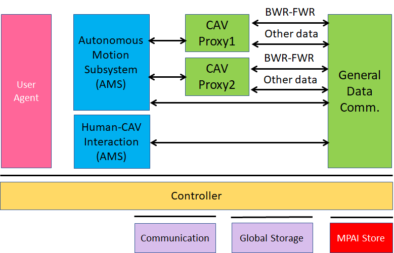
Figure 6 – The CAV-to-Everything Subsystem Reference Model
1.3.3 Input and output data
1.3.3.1 CAVs within range
Table 6 gives the data types a CAV broadcasts to CAVs in range.
Table 6 – I/O data of CAV-to-Everything
| Input Data | From | Comments |
| Basic World Representation | Other CAVs | A digital representation of the Environment created by ESS. |
| CAV Identity | Other CAVs | Digital equivalent of today’s plate number. Includes Manufacturer and Model information. |
| CAV Intention | Other CAVs | The Path and other motion data relevant to other CAVs |
| Full World Representation | Other CAVs | A digital representation of the Environment created by fusing all available Basic World Representations. |
| Information Messages | Other CAVs | Typical messages a CAV can broadcast. Sources of messages potentially important for CAVs are given by [37, 38]
1. CAV is an ambulance. 2. CAV carries an authority. 3. CAV carries a passenger with critical health problem. 4. CAV has a mechanical problem of an identified level. 5. Works and traffic jams ahead 6. Environment must be evacuated 7. …. |
| Output Data | To | Comments |
| Basic World Representation | Other CAVs | Same as input for all other input data. |
| Full World Representation | Other CAVs | A digital representation of the Environment obtained from the fusion of all available Basic World Representations. |
1.3.3.2 CAV-aware equipment
Such equipment are traffic lights, roadside units, vehicles with CAV communication capabilities.
- Identity and coordinates (exact coordinate reference).
These equipment can have one of the following functions:
- Act as any other CAV in range.
- Authority to organise motion of CAVs in range.
1.3.3.3 Other non-CAV vehicles
Other vehicles can be scooters, motorcycles, bicycles, other non-CAV vehicles, possibly transmitting their position as derived from GNSS. No response capability is expected. Vehicle may also have the capability to transmit additional information, e.g., identity, model, speed.
1.3.3.4 Pedestrians
Their smartphones can transmit their coordinates as available from GNSS. No response capability is expected.
1.3.4 AI Modules
Table 11 gives the AI Modules of Autonomous Motion Subsystem.
Table 7 – AI Modules of CAV-To-Everything Subsystem
| AIM | Function |
| General Data Communication | Communicates with non-CAV sources |
| CAV Proxy | Forwards data of
|
1.4 Autonomous Motion Subsystem (AMS)
1.4.1 Use Case description
The typical series of operations carried out by the Autonomous Motion Subsystem (AMS) is described below. Note that the sequential description does not imply that an operations can only be carried out after the preceding one has been completed.
- Human-CAV Interaction requests Autonomous Motion Subsystem to plan and move the CAV to the human-selected Pose. Dialogue may follow.
- Computes the Route satisfying the human’s request.
- Receives the current Basic World Representation from Environment Sensing Subsystem.
- While moving, CAV
- Transmits the Basic World Representation and other data to CAV-to-Everything.
- Receives Basic World Representations and other data from CAV-to-Everything.
- Produces the Full World Representation by fusing its own Basic World Representation with those from other CAVs in range.
- Plans a Path connecting Poses.
- Selects behaviour to reach intermediate Goals acting on information about the Goals other CAVs in range intend to reach.
- Defines a Trajectory that
- Complies with general traffic rules and local traffic regulations
- Preserves passengers’ comfort.
- Refines Trajectory to avoid obstacles.
- Sends the Motion Actuation Subsystem Commands to take the CAV to the next Goal.
- Stores the data resulting from a decision (Route Planner, Path Planner etc.)
The AMS should be designed in such a way that different levels of autonomy, e.g., those indicated by SAE International [9], are possible depending on the amount and level of available functionalities.
1.4.2 Reference architecture
Figure 7 gives the Autonomous Motion Subsystem Reference Model.
A human activates the CAV requesting to be transported to a waypoint. This activates the Route Planner and the Path Planner which requests the Full World Representation to Full World Representation Fusion which receives and fuses the Basic World Representations from its own and other CAVs’ Environment Sensing Subsystems. The chain Behaviour Selection-Motion Planner-Obstacle Avoider eventually generates a command which is sent to Motion Actuation Subsystem. The decisions of the said chain are recorded.
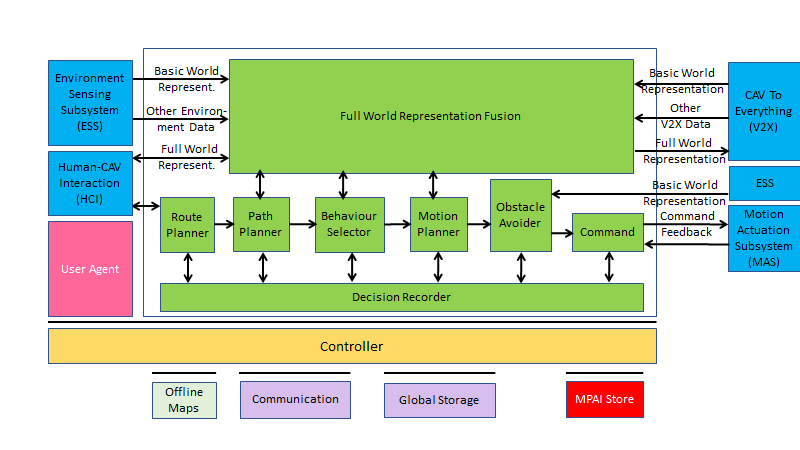
Figure 7 – Autonomous Motion Subsystem Reference Model
1.4.3 Input and output data
Table 8 gives the input/output data of Autonomous Motion Subsystem.
Table 8 – I/O data of Autonomous Motion Subsystem
| Input data | From | Comment |
| Human Command | Human-CAV Interaction | Human commands, e.g., “take me home” |
| Basic World Representation | Environment Sensing Subsystem | CAV’s Environment representation. |
| Other Environment Data | Environment Sensing Subsystem | E.g., temperature, air pressure. |
| Other V2X Data | CAV To Everything | Other CAVs and vehicles, and roadside units. |
| Command Feedback | Motion Actuation Subsystem | CAV’s response to Command |
| Output data | To | Comment |
| AMS Response | Human-CAV Interaction | MAS’s response to AMS Command |
| AMS Command | Motion Actuation Subsystem | Macro-instructions, e.g., “in 5s assume a given State”. |
| Full World Representation | CAV To Everything | For information to other CAVs |
1.4.4 AI Modules
Table 9 gives the AI Modules of the Autonomous Motion Subsystem.
Table 9 – AI Modules of Autonomous Motion Subsystem
| AIM | Function |
| Route Planner | |
| Path Planner | Generates a set of Paths, considering
1. Current Route. 2. State. 3. Full World-Representation. 4. Traffic Rules. |
| Behaviour Selector | Sets a Goal with a Driving Behaviour, to be reached within the Decision Horizon time frame. |
| Motion Planner | Defines a Trajectory, from the current State to the current Goal following the Behaviour Selector’s Path to the extent possible, satisfying the CAV’s kinematic and dynamic constraints, and considering passengers’ comfort. |
| Obstacle Avoider | Defines a new Trajectory to avoid obstacles. |
| Command | Instructs the CAV to execute the Trajectory considering the Environment conditions. |
| Full World-Representation Fusion | Creates an internal representation of the Environment by fusing information from itself, CAVs in range and other transmitting units.. |
1.5 Motion Actuation Subsystem (MAS)
1.5.1 Use Case description
The Motion Actuation Subsystem:
- Transmits information gathered from its sensors and its mechanical subsystems to Environment Sensing Subsystem.
- Receives instructions from Autonomous Motion Subsystem.
- Translates such instructions into specific commands to its own mechanical subsystems, e.g., road wheels, wheel motors, brakes.
- Receives feedbacks from its mechanical subsystems.
- Packages feedbacks into high-level information.
- Send high-levelinformation to Autonomous Motion Subsystem.
1.5.2 Reference architecture
Figure 8 represents the Motion Actuation Subsystem Reference Model.
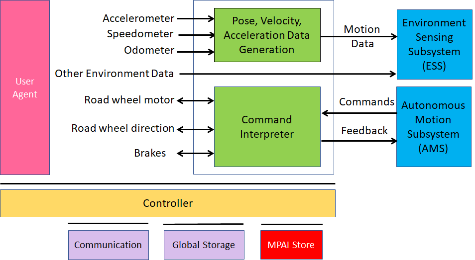
Figure 8 – Motion Actuation Subsystem Reference Model
1.5.3 Input and output data
Table 10 gives the input/output data of Motion Actuation Subsystem.
Table 10 – I/O data of Motion Actuation Subsystem
| Input | Comments |
| Odometer | Provides distance data. |
| Speedometer | Provides instantaneous velocity. |
| Accelerometer | Provides instantaneous acceleration. |
| Other Environment data | Provide other environment data, e.g., humidity, pressure, temperature. |
| Road Wheel Motor | Forces road wheels rotation, gives feedback. |
| Road Wheel Direction | Moves road wheels by an angle, gives feedback. |
| Brakes | Acts on brakes, gives feedback. |
| AMS Commands | High-level motion command. |
| Output | Comments |
| Motion data | Position, velocity, acceleration. |
| Other data | Other environment data. |
| MAS Feedback | Feedback from Command Converter during and after Command execution |
1.5.4 AI Modules
Table 11 gives the AI Modules of Autonomous Motion Subsystem.
Table 11 – AI Modules of Motion Actuation Subsystem
| AIM | Function |
| Pose-Velocity-Acceleration Data Generation | |
| Command Interpreter |